Fitting A Blitz Dual-SBC Spec-R To An Evo VI
Article by Frosty.
Preface:
This guide shows how to fit a Blitz Dual-SBC Spec-R boost controller to an Evo VI GSR. The procedure to fit the Spec-S should be almost identical, but with a maximum recommended boost level of 1.2 bar, I doubt many owners would fit the Spec-S anyway! Although this article is written around the Evo VI GSR, fitting the controller to other Evo models should be very similar (and probably identical on the IV and V). Lastly, this method assumes you wish to mount the unit in the centre console just below the head unit. If you have another location in mind then you should check the cable lengths and grommet locations before starting.
Disclaimer:
This is the method of installation I chose when fitting my own boost controller. It is by no means the correct way, or the method endorsed by Blitz, nor anyone else. You follow these guidelines at your own risk. I will be held in no way responsible for any damage that occurs to any vehicle as a result of following part or all of this guide.
Step 1:
The first (and probably the hardest) job is to run 2 cables from the cars interior to the engine compartment. The first cable is surrounded by plastic ribbed hose and connects the control unit to the square box with the IN and OUT ports. The second is the vacuum hose which connects to the back of the control unit.
Start by loosening the wheel nuts and jacking up the passenger side (nearside) front wheel, and then remove the wheel. It's probably best to use an axle stand once the car is actually up in the air as you will be jumping in and out of the car quite a bit.
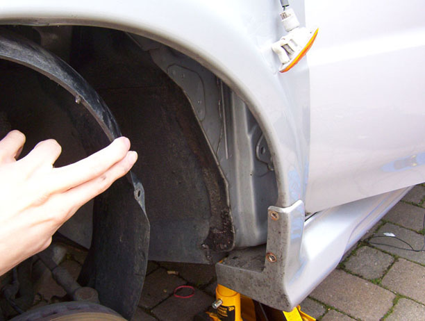
Undo the 4 nuts towards the rear of the wheel arch (See Figure 1). It's best to use a socket instead of a screwdriver. The arch is quite flexible and so with a little persuasion it should pull free as shown in Figure 2.
Figure 1:
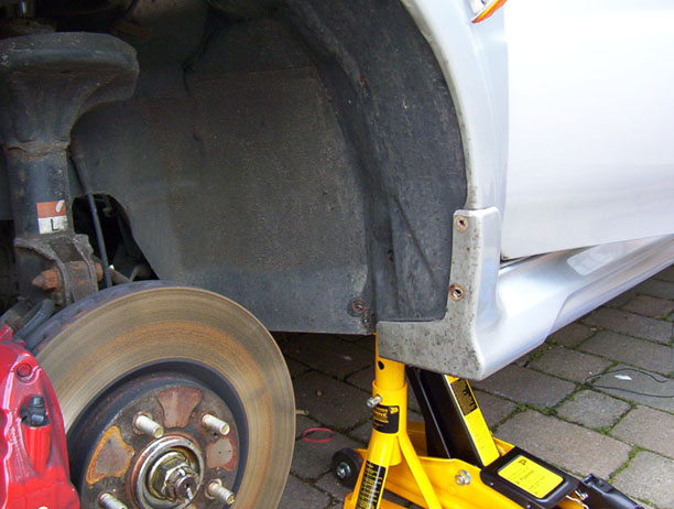
Figure 2:
Step 2:
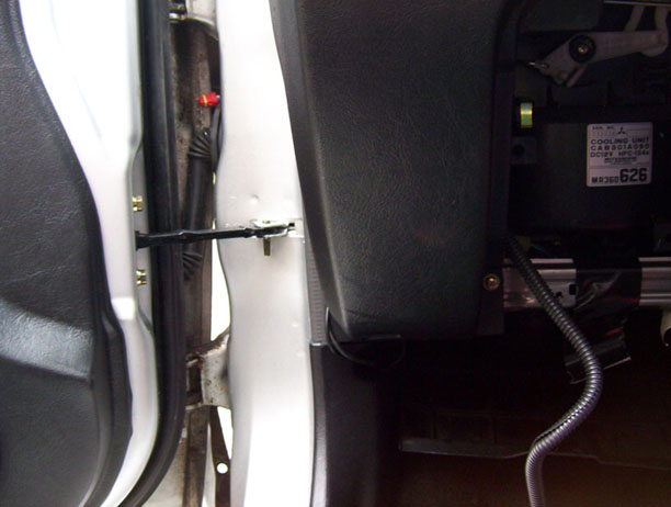
Open the passenger door fully and you will see the grommet you need to go through (Figure 3). Pop this grommet out. Note: You do not need to remove the side-repeater as pictured - I only did this to look for a grommet before removing the wheel arch.
Open the glove-box and remove it by squeezing the sides and pulling it free. You can undo the 2 screws at the bottom if you need more room. Poke the small-connection end of the cable through to the giant hole where the glove-box used to be and through the gap near the ECU so it pops out through the hole where the grommet used to be. Now do the same with the small black vacuum hose. Figure 3 shows the route the cables must take.
Cut a hole in the grommet big enough for a the plug on the end of the cable to pass through. A cross shape works well. Now thread the cable and the black hose through it.
Figure 3:
Step 3:
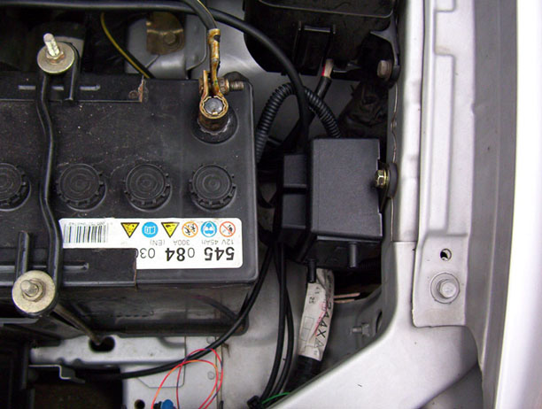
Pull these cables through the grommet with plenty of slack to play with and then route them above the wheel arch you just removed. A bit of patience and they should end up next to your battery - pull them through some more. At this point you can connect the cable to the black box and screw it into the engine bay. I found a screw hole next to the battery which was perfect.
Figure 4:
Step 4:
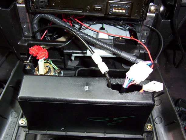
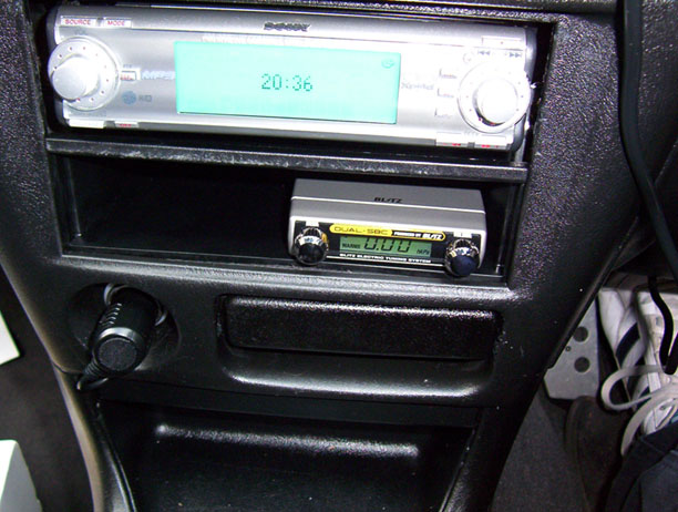
Remove the trim surrounding the stereo by pulling it (remove the ashtray first) - it should pop straight off. Now you can route the other end of the cables through to this compartment as shown in Figure 5. I unscrewed the bottom part of the double-DIN adapter and spot-drilled it to give the cables and vacuum hose a path to the controller. Re-attach the drilled panel and poke the cables through it. Connect them to the Blitz unit and stick it down.
Now you need to power the unit so ensure the ignition is off. I used the switched power source of the cigarette lighter socket for +12v and earth. The two red Scotch-Locks make this very easy. Tidy up the wiring, stick the controller into place and re-attach the trim panel.
Figure 5:
Step 5:
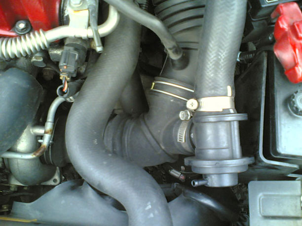
The Blitz controller needs a manifold vacuum/pressure source. The ideal hose for this is the hose that the dump valve uses. Use the T-Piece provided and connect the thin black hose to it. I had to extend the black hose with some thicker hose so a) I had enough cable length, and b) the thin cable would not connect up to the T piece.
Figure 6 shows the pipe removed before the T-piece was fitted. If any of the pipes are being stubborn then dip them in boiling water for a couple of minutes. You should then be able to fit the very small pipe into the larger pipe.
Figure 6:
Step 6:
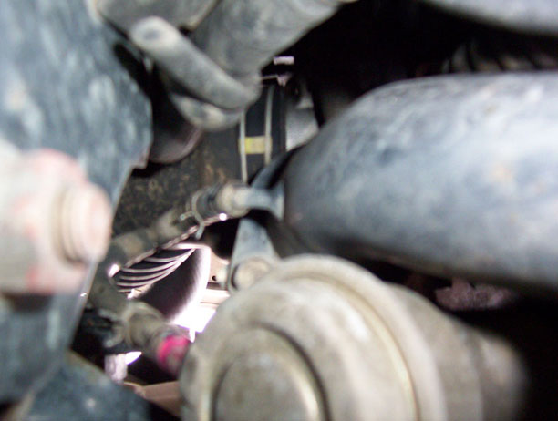
Looking down at the turbo you can see the two hoses that need removing. They actually come from the same source via a T-piece. One end is connected to the turbo compressor housing, and the other is connected to the wastegate actuator (bronze coloured thing). Figure 7 shows the two pipes, and Figure 8 shows them again from underneath (although somewhat out of focus).
I found this much easier working from underneath the car. Remove both the pipes - not from the T-piece but from the actual components so that there is no pipe left. They will be very stubborn, and a flathead screwdriver will help a lot.
Figure 7:
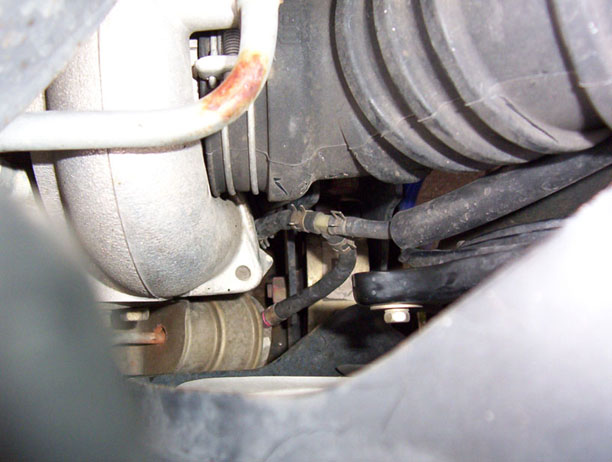
Figure 8:
Step 7:
With the pipes removed you can now attach the supplied blue hose from the black box to the turbo.
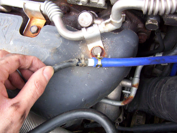
The blue pipe is too big to fit on the actuator and compressor outlet, so use some of the pipe you removed as well as the clamps. Connect the two bits of pipe with one of the white adapters supplied with the kit (see Figure 9). Cut the blue hose in half and make a second one with the same join to the smaller hose.
Connect one of the blue hoses to the IN port on the black box. Run this down to the turbo and connect it to the compressor housing outlet using a clamp.
Connect the other blue hose to the OUT port on the black box. Run this down to the turbo and connect it to the wastegate actuator using a clamp.
Figure 9:
Step 8:
Re-fit the glove-box, wheel arch and wheel. Now go have some fun!
Figure 10:
Setting up:
Clicky
Or search the forum for details on setting up.
Thanks to all those on the MLR who answered my countless question and helped me complete the installation.